We use cookies to provide you with an improved user experience and to personalize content. To learn more, see our Privacy Policy.
Free UPS ground shipping on all orders of $150 or more. Shop Now
hidden
Vacuum Switch Selection Guide
At Whitman, we offer an extensive selection of vacuum switches affording the end-user maximum versatility in a wide range of operating environments. Our preset switches are set at the factory to the specifications and parameters to fit our customers’ requirements. These switches are In-stock and available for same day shipping if ordered prior to 1pm EST. Our field adjustable switches allow our customers the flexibility of easily setting the switch parameters in the field as driven by the needs of the project. These switches can be designed to meet the needs of your specific application, and are available to ship in two weeks or less.
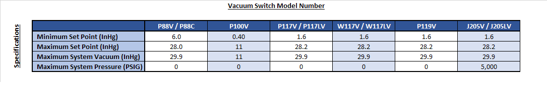
The below chart gives an overview of our product catalog at Whitman, and the functionality of each of our switches. Depending on your desired set point, and maximum system pressure, you will find a switch that will meet your specific needs and exceed your expectations.
Steps Required for Identifying the Right Vacuum Switch for your Application:
The below commentary outline all the steps needed in identifying the right pressure switch for your applications. If you are confused by any of the terminology or have additional questions, please reference our Switch Glossary or reach out to our engineering team at [email protected] :
Step 1: Identify the maximum system pressure on your application
Your maximum system pressure is used to determine the sensor or spring code, and is of the upmost importance to preserve switch functionality and integrity. Over pressures and spikes must not exceed the rated proof pressure on the switch, or the switch will not meet performance standards. Your maximum system pressure can be found in Table A of the “Sensor Code and Performance Tables” on each page.
In the table below, you can quickly identify the switch or switches that would be ideal for your application by understanding your maximum system pressure.
Step 2: Identify your Set Point Pressure and if on “Increasing” or “Decreasing” vacuum
The set point is the exact point at which the electrical switching element functions (turns the application on or off). This is generally expressed in Inches of Mercury (InHg). The Set point range is the range within which the switch can be set from the lowest to the highest point. As the end-user, you must specify if you want the set point to open or close on increasing or decreasing vacuum.
Step 3: Select a sensor code that applies to the maximum system pressure and set point range desired for your application
The sensor code can be found in the “Sensor Code and Performance Tables” for each switch, and will correlate to a specific maximum system pressure and set point range.
Step 4: Determine your Set Point Option
The vast majority of our models can be adjusted in the following ways:
C-set: Customer set, field adjustable
K-set: Factory pre-set to customer specifications, but field adjustable
F-set: Factory set to customer specifications, non-adjustables
When ordering a “K” or “F” set, the customer must specify the set point and if desired on increasing or decreasing pressure.
Step 5: Select your Electrical Amperage and Contact Selection
Reference the Electrical Switch Selection Tables to determine the most appropriate amperage and contact material for your application. All electrical switches are Single Pole Double Throw (SPDT) but may be used as Single Pole Single Throw (SPST). If used as SPST, switching function must be specified.
Step 6: Select your Electrical Interface
Reference our Electrical Interface Options to determine the interface most desired for your application.
Step 7: Select your Wire Length if longer than 12” (Standard) is desired
Step 8: Confirm Wetted Materials are Compatible with Fluid and Environment
The wetted and non-wetted materials of each Whitman switch are specified on that specific product page. Please ensure the construction materials will be compatible with the media and immediate environment of your specific application.
Step 9: Select any additional Options
At Whitman, we allow the end-user any number of additional add-ons to improve switch functionality while limiting the steps necessary between ordering of a switch and installing it in your application. Our additional add-ons include:
Bar Code:
Boot on Jacketed Wire:
Calibrated Switch:
¼” Convoluted Condit + Electrical Tape
3/8” Convoluted Conduit + Electrical Tape:
Customer P/N on label
Helium-Leak Test
Inspection Tag
Loctite Vibraseal on fitting
Non-Potted Interface (L only)
Spike Arrestors:
Port Threat Adaptors
Conduit Adaptors
Special Packaging Instructions:
Teflon Tape on Fitting
Additional Wire (Non-jacketed)
Additional Wire (Jacketed)
Wire – 18 AWG Type SXL
Wire Labels
Wire Bundle Labels – Military Grade Shrink Style
Next in-line fee
Quality at Whitman is proven both by a reliability rate substantially higher than industry standards and an ISO 9001 certified Quality Management System. This is fostered both by the uncommon capabilities of our sales personnel who seek detailed application information before recommending the proper model, and by the feedback from our technical people who continually test our products in a variety of conditions over lengthy periods of time.
We appreciate your interest in our line of products, and we are confident that our switch performance will exceed your expectations.